ASR1001-X Aggregation Service Router
| Model: | ASR1001-X Aggregation Service Router |
| Detail: |
Cisco ASR1000-series router, Build-in Gigabit Ethernet port, 6 x SFP ports, 2 x SFP+ ports, 2.5G system bandwidth
|
| Product Code | Cisco ASR 1001-X |
| Rack Height | 1RU |
| System Bandwidth | 2.5G (default) / 5G, 10G, 20G (upgrade) |
| Router Processor (RP) | Quad-core 2.13Ghz processor |
| Build-in Gigabit Ethernet port | 6 x SFP ports, 2 x SFP+ ports |
| Redundancy | Software (license purchase separately) |
| SIP and Ethernet line card | Integrated in chassis; not upgradable |
| Embedded hardware-based encryption | up to 8-Gbps crypto support throughput |
| Rack-mounting | 19-inch |
| DRAM Memory | 8 GB |
| Flash Memory | 8 GB |
| Shared port adapters | 1 SPA slot |
| External USB flash memory | 1-GB USB flash-memory support |
AED234,799.00
Cisco ASR 1000-X is designed for high-end enterprise, data center, service provider edging network in order to handle explosive traffic through the network. It supports only software redundancy, and it is based on a Quad-core 2.13GHz processor with 4GB memory, 8GB flash memory, 1 SPA bay, SPA interface processor 10 (SIP10).
This ASR1001-X is similar with the ASR1001-X=. The ASR1001-X= is a spare one.
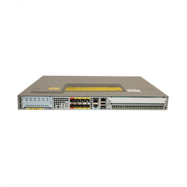
Figure 1 shows the appearance of the Cisco ASR 1001-X.
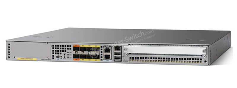
Figure 2 shows the front panel of Cisco ASR 1001-X.

Note:
① NIM slots
② CON—One mini eUSB por
③ STAT—Status LED
④ CRIT LED—Critical alarm indicator; MAJ LED—Major alarm indicator; MIN LED—Minor alarm indicator
⑤ 6 x SFP ports, 2 x SFP+ ports
⑥ CON—One RJ-45/RS-232 compatible console port
⑦ USB port 1
⑧ USB port 0
⑨ Shared port adapter slot
⑩ MGMT—One RJ-45 10/100/1000 management Ethernet port.
⑪ AUX—One RJ-45/RS-232 compatible auxiliary port
⑫ PWR—Power LED
·Six built-in 1 GE SFP-only interfaces (do not support SFP+), and two built-in 10 GE SFP+ interfaces (support only 10-GE rate)
Table 2 shows some LEDs’ Descriptions.
| LEDs | Color | Description |
| PWR
(Power) |
Solid green | All power requirements are within specification. |
| Off | The router is in standby mode. | |
| STAT
(System Status) |
Solid green | Cisco IOSD and other required processes have loaded successfully and are operating. |
| Yellow | ROMMON is running (including a permanent failure of RP software) or the Process Manager has declared a critical RP process (including IOSD) dead. A user can log in to recover. | |
| Red | Occurs during system failure or power-up. | |
| CRIT
(Critical) |
Solid Red | Functions as a critical alarm indicator. The LED is lso a solid red during the boot process. |
| MAJ
(Major) |
Solid Red | Major alarm indicator. |
| MIN
(Minor) |
Amber | Minor alarm indicator. |
Figure 3 shows the back panel of ASR1001-X.
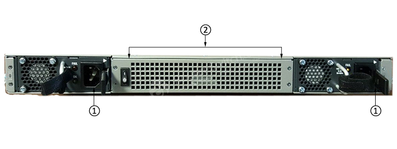
Note:
① Two power supplies, either two AC power supplies or two DC power supplies are accessed from the rear of the router and are hot-swappable.
② Four internal fans draw cooling air into the chassis and across internal components to maintain an acceptable operating temperature.
The Configuration
The ASR1001-X should be configured with some modules and accessories for normal operation.
Table 3 shows the recommended configuration.
| Items | Quantity | Descriptions |
| ASR1001-X-PWR-AC | 2 | Cisco ASR1001-X AC Power Supply |
| CAB-L620P-C13-US | 2 | Power Cord, 250VAC, 15A, NEMA L6-20 to C13, US |
| SASR1K1XU-313S | 1 | Cisco ASR1001-X IOS XE UNIVERSAL – NO ENCRYPTION |
| NIM-BLANK | 1 | Blank faceplate for NIM slot on Cisco ISR 4400 |
| SPA-BLANK | 1 | Blank Cover for regular SPA |
| M-ASR1001X-8GB | 1 | Cisco ASR1001-X 8GB DRAM |
| ASR1K-OTHER | 1 | ASE1K-other applications for Enterprise or SP-Tracking only |
| L-SLASR1-IPB= | 1 | Cisco ASR1001 License L-SLASR1-IPB= Cisco ASR 1000 IP BASE E-Delivery PAK |
ASR1001-X Specifications |
|
| Physical specifications
Note: Depth applies to chassis edge-to-edge dimension and does not include protrusions such as card handles, power-supply handles, and cable management brackets. Refer to the applicable hardware installation guide for additional details. |
Height: 1.71 in. (43.43 mm)
Width: 17.3 in. (439.42 mm) Depth: 18.17 in. (461.5 mm) Weight: ● 25 lb (11.35 kg) fully loaded Note: The Cisco ASR 1001-X Router has the route processor, ESP, and SIP integrated. |
| Default memory | 8-GB DRAM shared across route processor, ESP, and SIP |
| Number of SIPs or Ethernet line cards supported | Integrated in chassis |
| Shared port adapters | 1 single-height SPA slot |
| Ethernet port adapters | N/A |
| Cisco ASR 1000 Series ESP | Integrated in chassis |
| Route processor | Integrated in the chassis: Cisco ASR 1001-X Series Route Processor with Quad Core Processor |
| Redundancy | Software: Yes |
| Built-in Gigabit Ethernet ports | Yes: 6 Gigabit Ethernet Small Form-Factor Pluggable (SFP) ports |
| Built-in 10 Gigabit Ethernet port | Yes: Two 10 Gigabit Ethernet Small Form-Factor Plus Pluggable (SFP+) ports
Note:Built-in 10-GB ports cannot be reduced to 1-GB speed. |
| Network interface module | Yes |
| Cisco ASR 1000 Series | Cisco ASR 1001-X |
| ESP support | Cisco ASR 1000 Series 2.5-Gbps ESP (default)
Upgradable through a software-activated feature license to 5, 10, or 20 Gbps |
| ESP bandwidth | 2.5 to 20 Gbps |
| ESP memory | Share the same control memory on route processor |
| SIPs and Ethernet line cards | Integrated in chassis; not upgradable |
| Embedded hardware-based encryption | Yes: Up to 8-Gbps crypto support throughput |
| Minimum Cisco IOS XE Software release | Cisco IOS XE Software Release 3.12.0 |
| Rack-mounting | Yes: 19-inch |
| Wall-mounting | No |
| External USB flash memory | 1-GB USB flash-memory support |
| Redundant power supply | Yes: Dual power supplies by default; option of either AC or DC power supply
Note: A mix of one AC and one DC power supply is not supported. |
| Power input | Worldwide ranging AC input range (85 to 264 VAC)
Worldwide ranging DC (-40 to -72V; 48V nominal) |
| Power consumption | ● Maximum (DC): 242W
● Maximum (AC): 250W ● Maximum (out): 250W |
| Airflow | Front-to-back |
| Operating temperature (nominal) | 32 to 104°F (0 to 40°C) |
| Operating temperature (short-term) | 32 to 122°F (0 to 50°C) |
| Operating humidity (nominal) (relative humidity) | 10 to 85% |
| Operating humidity (short-term) | 5 to 90% |
| Storage temperature | -40 to 150°F
(-40 to 70°C) |
| Storage humidity (relative humidity) | 5 to 95% |
| Operating altitude | -500 to 10,000 feet (152 to 3048 meters) |
| Network Equipment Building Standards (NEBS) | GR-1089 and GR-63 (in progress) |
| EMC standards | ● FCC 47 CFR Part 15 Class A
● VCCI Class A ● AS/NSZ Class A ● ICES-003 Class A ● EN55022/CISPR 22 Information Technology Equipment (Emissions) ● EN55024/CISPR 24 Information Technology Equipment (Immunity) ● EN300 386 Telecommunications Network Equipment ● (EMC) ● EN50082-1/EN61000-6-1 Generic Immunity Standard |
| Safety Standard | UL60950-1
CSA C22.2 No. 60950-1-03 EN 60950-1 IEC 60950-1 AS/NZS 60950.1 |
Based on 0 reviews
Only logged in customers who have purchased this product may leave a review.
 04 3550600
 052 7036860
 info@techsouq.com

There are no reviews yet.