 04 3550600
 052 7036860
 info@techsouq.com
Cisco Catalyst 2960-S FlexStack – Description, Usage, and Best Practices White Paper
30 in stock
AED3,299.00
30 in stock
Cisco Catalyst 2960-S FlexStack – Description, Usage, and Best Practices White Paper
Introduction
Cisco® FlexStack stacking for Cisco Catalyst® 2960-S Series Switches provides a true stacking solution with all switches in a FlexStack stack acting as a single![]() switching unit. FlexStack provides a unified data plane, and single
switching unit. FlexStack provides a unified data plane, and single![]() configuration for a group of stacked Cisco Catalyst 2960-S switches.
configuration for a group of stacked Cisco Catalyst 2960-S switches.
FlexStack lowers the total cost of ownership with built-in 1:N redundancy, high availability, and preprovisioning, not available in standalone switches. High-availability features![]() such as EtherChannel and FlexLinks will work across stack members, increasing uptime and network connectivity.
such as EtherChannel and FlexLinks will work across stack members, increasing uptime and network connectivity.
As part of the Borderless Network architecture, FlexStack allows scalable provisioning and management to deploy any number of switches quickly and easily![]() .
.
Why Stack Ethernet Switches?
Stacking Ethernet switches reduces the network administrator’s total cost of ownership. The cost of maintaining the network is decreased because there are fewer devices to manage![]() , and the network uptime is increased with built-in redundancy.
, and the network uptime is increased with built-in redundancy.
Figure 1 shows two ways to deploy Ethernet switches at the access![]() layer. In each case four switches are connected to a Cisco Catalyst 6509 Switch. The deployment scenario on the left shows four switches that are colocated in the same wiring closet, but are not stacked. Each standalone switch on the left has two uplinks to the distribution layer switch that are combined in an EtherChannel group. The four switches on the right are stacked together with FlexStack (FlexStack links show in red). The stack has four uplinks to the distribution layer switch. Because FlexStack supports EtherChannel grouping of Ethernet interfaces across the stack members, the four uplinks are grouped together into a single EtherChannel group. All the benefits of EtherChannel grouping are retained when switches are placed into a stack.
layer. In each case four switches are connected to a Cisco Catalyst 6509 Switch. The deployment scenario on the left shows four switches that are colocated in the same wiring closet, but are not stacked. Each standalone switch on the left has two uplinks to the distribution layer switch that are combined in an EtherChannel group. The four switches on the right are stacked together with FlexStack (FlexStack links show in red). The stack has four uplinks to the distribution layer switch. Because FlexStack supports EtherChannel grouping of Ethernet interfaces across the stack members, the four uplinks are grouped together into a single EtherChannel group. All the benefits of EtherChannel grouping are retained when switches are placed into a stack.

Stacking Ethernet switches provides the network administrator with three major operational benefits:
● Single![]() point of management: All switches in the stack are managed as one.
point of management: All switches in the stack are managed as one.
● Built-in redundancy and high availability: The high-speed FlexStack connections![]() provide redundant communication for each stack member to every other member.
provide redundant communication for each stack member to every other member.
● Scalable to fit network needs: Installation![]() of a new switch to the stack is easy. As the need for additional access ports grows, adding a new switch to an existing stack is easier and faster than adding a new standalone switch to the network.
of a new switch to the stack is easy. As the need for additional access ports grows, adding a new switch to an existing stack is easier and faster than adding a new standalone switch to the network.
The first operational benefit is fewer devices to manage. Multiple physical switches in a stack appear as a single![]() logical switch. This eases management overhead because there are fewer devices in the network to manage. A single IP address is used to manage the logical switch. All manageable entities (for example, Ethernet interfaces and VLANs) on all physical switches can be configured and managed from the logical switch. The logical switch will appear as a single entity in the network. In a Layer 2 network, the logical switch will appear as a single spanning-tree entity.
logical switch. This eases management overhead because there are fewer devices in the network to manage. A single IP address is used to manage the logical switch. All manageable entities (for example, Ethernet interfaces and VLANs) on all physical switches can be configured and managed from the logical switch. The logical switch will appear as a single entity in the network. In a Layer 2 network, the logical switch will appear as a single spanning-tree entity.
The second operational benefit that stacking provides is built-in redundancy and increased availability. Data path redundancy is built into the stacking architecture as there are two physical paths between any two stack members. Connecting stack members with the stacking cables provides data path redundancy for all stack members. Stacking increases Ethernet switch availability by providing redundancy for both the physical switch and the uplink. Because different physical switches will connect to the upstream network, losing one switch or one uplink interface does not prevent connectivity to the network. Since the logical switch has multiple uplinks, the logical switch still has network connectivity because at least one uplink is still active![]() .
.
In a logical switch, a single physical switch is acting as the stack master. The stack master manages all physical switches, including itself. If the master fails, another member automatically![]() becomes the stack master following a well-documented election process (covered later). The configuration of the stack is preserved through a single switch failure or a reboot of all stack members. FlexStack provides 1:N redundancy for the stack master, with the ability for any physical switch to back up the acting master. (See Figure 2.)
becomes the stack master following a well-documented election process (covered later). The configuration of the stack is preserved through a single switch failure or a reboot of all stack members. FlexStack provides 1:N redundancy for the stack master, with the ability for any physical switch to back up the acting master. (See Figure 2.)

Flexibility of FlexStack allows for modular stacking capability. Cisco Catalyst 2960-S switches can be added to a stack at any time by adding the optional FlexStack module. As the demand for Ethernet access ports increases, Cisco Catalyst 2960-S switches can be stacked together either to create a new stack or to add new Cisco Catalyst 2960-S switches to an existing stack. This flexibility provides investment protection for the network administrator, who can add additional stack members as needed.
Adding members to a stack and replacing physical units are much easier when multiple switches are combined into a FlexStack group. Since the stack retains the configuration, there is no need to back up the configuration prior to removing the switch. Conversely, when a new member is inserted into the stack, the configuration of the stack is pushed to the new member. The network administrator need not explicitly recover the switch configuration since the stack took care of it.
Stacking and Clustering
Stacking is not clustering. Clustering is a technology available on Cisco Catalyst fixed Ethernet switches that allows the network administrator to use a single public IP address to manage multiple physical switches. Clustering was created to assist network administrators by having a single point of management as well as in preserving valuable public IP addresses needed to manage the Ethernet switches. Stacking is much more than a single point of management and IP address preservation because it offers redundancy, availability, and ease of management. Cisco Catalyst 2960-S supports clustering as well as stacking.
What Is FlexStack?
FlexStack is the name of the stacking technology used by the Cisco Catalyst 2960-S series of fixed Ethernet switches. FlexStack is specific to Cisco Catalyst 2960-S switches, and only Cisco Catalyst 2960-S Series Switches use FlexStack.
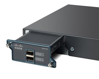
FlexStack is composed of hardware components and the FlexStack protocol. The hardware components are the FlexStack module (Figure 3) and the FlexStack cables. The FlexStack module supports two FlexStack ports. The FlexStack module is inserted into the rear of the Cisco Catalyst 2960-S Series Switch. Two FlexStack cables, inserted into the FlexStack module, are used per Cisco Catalyst 2960-S switch to provide data path redundancy. Using FlexStack cables, the physical members of the stack form a ring, providing the built-in redundant data path for each member of the stack.
The FlexStack protocol allows the FlexStack members to behave as one logical switch. The FlexStack protocol runs on each member. The FlexStack protocol is used by the master switch to manage the other members. The master tracks the presence of each member, the member’s availability, the Cisco IOS® Software image, and the status of each member’s FlexStack connections.
Stacking with FlexStack on the Cisco Catalyst 2960-S Series Switches is optional. In order for the switches to stack, a separate FlexStack module must be inserted in the rear of the switch. Without this module, FlexStack cannot function. Figure 3 shows a partially inserted FlexStack module in the rear of the Cisco Catalyst 2960-S Series Switch. The FlexStack module is hot swappable.
A single FlexStack connection between two members is a full duplex 10Gbps connecton. Each Cisco Catalyst 2960-S member supports two FlexStack connections. Each FlexStack member can simultaneously send and receive Ethernet traffic over both stack links at line rate, effectively giving 20Gbps of stack bandwidth per member.
Up to four switches can stacked together using FlexStack to form a single logical switch. Logical switch is another term used to identify a stack of switches. There are multiple physical switches acting as a single unit. This single unit behavior is a logical switch.
Cisco Catalyst 2960-S switches running FlexStack use a hop-by-hop method of transferring Ethernet packets across the stack. Packets traverse the stack by going from one member to another over the FlexStack links until the packet reaches its destination. This is the same behavior as multiple standalone Ethernet switches forwarding packets from one switch to another.
FlexStack Cabling
Special cables are used to connect Cisco Catalyst 2960-S Series Switches together in a stack. These special FlexStack cables can only be used to stack Cisco Catalyst 2960-S switches with other Cisco Catalyst 2960-S switches. Figure 4 shows a picture of two FlexStack cables connected to a fully inserted FlexStack module. Notice how the tabs on the cables are on opposite sides of each other. The FlexStack cables are keyed as well. Besides the tabs needing to be away from each other, the keying of the metal portion of the connector prevents the cable from being connected incorrectly.

When each member in the FlexStack group has two operational FlexStack links, then the stack is operating in a fully redundant mode. The dual FlexStack connections from each member to two other members are what provide the redundancy. Should any single FlexStack connection break or cease to operate, then the switches in the stack will use the remaining FlexStack connection that is provided.
Deployment Topologies
Figure 5 shows a three-member stack with full bandwidth and with redundant FlexStack connections. Each member in Figure 5 has 20Gbps of stack bandwidth and is fully redundant.

When one FlexStack Link is not present, the stack still functions. Figure 6 shows a stack with incomplete FlexStack cabling. In Figure 6, all data traffic passes through the middle member. This stack is operating in a nonredundant mode. This stack provides only half of the possible bandwidth between members and does not have redundant connections. Only the middle member has 20Gbps stack bandwidth. The top and bottom members are operating at 10Gbps stack bandwidth.

Three different FlexStack cable lengths are available, shown in Table 1.
Table 1. Cable Lengths
|
Product ID |
Length |
Description |
|
CAB-STK-E-0.5M |
0.5 meters |
This is the default cable that ships with the FlexStack module. |
|
CAB-STK-E-1M |
1.0 meters |
|
|
CAB-STK-E-3M |
3.0 meters |
|
The different lengths allow for deployment flexibility. Figure 7 shows how to stack four switches using only the 0.5-meter cables. The stack member connections are interweaved using the stack cables. No cable extends more than two stack members. The interweaving of the stack links still provides redundant connections for the stack.

Figure 8 shows the conventional cabling deployment. The 3.0-meter cable is used to complete the redundant ring connection by connecting the top member with the bottom member. The other connections connect to directly adjacent members using the 0.5-meter cables. The 3.0-meter cable is not the default cable shipped for FlexStack and must be ordered. See the Cisco Catalyst 2960-S data sheet for ordering information.

The 0.5-meter cable can be used to connect two Cisco Catalyst 2960-S switches that are 4 rack units away from each other. In a stack of four, with all four members racked directly on top of each other, 0.5-meter cables can be used to connect all stack members. When stack members are more than 4 rack units apart, then longer stack cables are required.
FlexStack Protocol
FlexStack protocol allows every stack member to be in constant communication with the adjacent member and with the stack master. Each member is aware of the operational state of every stack port in the stack. The FlexStack protocol allows the stack to react to changes in the operational state of a FlexStack connection (for example, a stack changes state to operationally down). Changes in a stack port’s operational status are pushed to all members as soon as the state change is detected. FlexStack protocol is used to detect new member additions as well as member removal. All stack operational status for members and interfaces is communicated to each member through the FlexStack protocol.
Because all management of the stack takes place on the stack master, member status and stack port connectivity information comes from the stack master too.
Role of the Stack Master
The stack master controls the configuration and is the central point for management. All Layer 2 protocol traffic (for example, VLAN Trunking Protocol [VTP], Dynamic Trunking Protocol [DTP] , Cisco Discovery Protocol, Link Layer Discovery Protocol [LLDP]) is forwarded to the master regardless of where the protocol packet ingresses. The master will also transmit all Layer2 protocol packets. If the egress interface is on another member, then the protocol packet is passed from the master along the stack to the destination member.
The same behavior is seen for management traffic. Simple Network Management Protocol (SNMP), HTTP, Telnet, and Secure Shell (SSH) Protocol type of management traffic is all forwarded to the master regardless of the ingress interface. The response from the master is sent through the stack to the destination interface.
On configuration changes, the stack master pushes a copy of the configuration to every member. This way all members have a copy of the saved configuration.
Stack upgrades occur on the master. The master pushes new Cisco IOS Software images to all members. Each member stores a copy of the Cisco IOS Software image on its local Flash.
FlexStack LED Operation
The LEDs on the front of the Cisco Catalyst 2960-S can be used to view stack operation. When multiple Cisco Catalyst 2960-S switches are stacked together, only the stack master will have the “MSTR” LED solid green. Other members of the same stack will have this LED dark.
To find the switch member number, press the mode button just below the LEDs until the stack LED goes green. At this point the LEDs over the Ethernet ports are used. The port number matching the member will start to blink. For member 2, port 2 will blink. For member 3, port 3 will blink. Depending upon the number of members in the stack (up to four) the other ports will go solid green. This allows the network administrator to see the number of stack members just from the LEDs over the ports.
When a switch is operating standalone, the MSTR LED will be solid green.a
| Weight | 10.5 kg |
|---|
Based on 0 reviews
Only logged in customers who have purchased this product may leave a review.


There are no reviews yet.